m/v Waterfall II
the Official Blog of the
Proposed Layout and Design
You should always draw a sketch or drawing to scale to make sure the finished product looks somewhat like it should. Also, consider the 'weight and balance'.
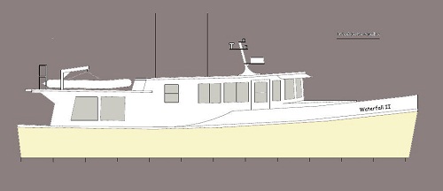
The profile was derived from the cross section drawing. The cross section measurements came from the blue prints and those taken on the boat. Since we are working with a boat that has many of the components already there, there are some limitations. As it is, I am very satisfied with the layout.
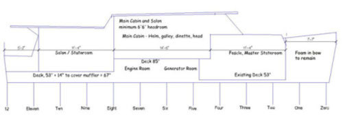
The foam in the bow will stay. The reason is that to go farther forward with the masterstateroom would make the bed have to be on one side with access to only one side of the bed. The floor level in the salon/stateroom needs to be raised 14 inches for a couple reasons. The muffler is on one side, we need more height for the fuel tanks under the floor and it needs to be high enough to sit on a sofa and see out comfortably.
Since we will be living on the boat for extended periods of time, roominess was a consideration. Large master stateroom, large galley/dinnette/helm/head area and a comfortable salon. That is why the salon doubles as a stateroom, there is no guest stateroom. The salon will have a closing door for privacy for those using it as a stateroom.
Since we will be living on the boat for extended periods of time, roominess was a consideration. Large master stateroom, large galley/dinnette/helm/head area and a comfortable salon. That is why the salon doubles as a stateroom, there is no guest stateroom. The salon will have a closing door for privacy for those using it as a stateroom.
Lower Plan - engine, generator, fuel and water tanks,
The layout of the lower plan view includes most of the "utilities". Here again we are working with components that are already in place. I see this as an advantage. In considering the layout the weight of the components need to be taken into account. From past experience I know that the stern of this hull can carry quite a load. The weight of the fuel tanks will be somewhat offset by the generator and water tank.
The layout of the lower plan view includes most of the "utilities". Here again we are working with components that are already in place. I see this as an advantage. In considering the layout the weight of the components need to be taken into account. From past experience I know that the stern of this hull can carry quite a load. The weight of the fuel tanks will be somewhat offset by the generator and water tank.
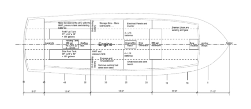
--The Engine is in place with the shaft connected. The engine will not be moved. It will need some flexible engine mounts and a flexible coupling to the shaft. The last boat we did move the engine to the next compartment forward. Two universal joints were installed in the shaft so the engine could remain at the same level. So, if you do want to move the engine it is possible to do with little difficulty or expense.
--The Water Tank can sit under the generator and use the stringers and one existing bulkhead. This will need to be a maximum of 350 gallons because of the weight. Originally I was going to use two tanks in the engine room but with more calculations of weight, I think the new location will balance out the weight better. Also, only one waterfill will be needed.
--The Fuel Tanks will be built with fiberglass and use the stringers aft of the engine room for sides. I feel that if built properly they will out last stainless steel or aluminum. There is no chance of corrosion and leaks. Since the deck is going to be raised in that area each tank will hold about 375 gallons of fuel. The fills will be on the back deck for convenience. I dislike standing on a 12 inch wide deck when fueling. The two existing fuel tanks will be removed.
--The Holding Tank is to be made of fiberglass and sit between the stringers just aft of the engineroom bulkhead. The shaft will go through the middle of the tank. This just happens to be the most convenient place.
--The Hot Water Tank and Pressure Tank will be installed in the engine room on the starbard side. I have opted for a 30 gallon Torrid tank with a 240v and engine water heat exchanger.
--The Heating Boiler and Air Conditioner will also go on the starbard side in the main engine room. The HWT, Pressure Tank, Heater, Airconditioner and the starting batteries will have to be arranged to offset the weight of the Washer/Dryer which will be in the salon on the Port side.
--The Bow Thruster tube will be installed just aft of the forward foamed compartment. This is a little aft from the last boat but this time we will not be removing any of the foam. It will still be forward enough to be effective. As a note, there is an "assist rudder" or "monkey rudder" just forward of the skeg that will be removed . I find that a monkey rudder is a little cumbersom to use.
Upper Level Plan - Living Areas
Main Cabin (pdf)
MasterStateroom (pdf)
Salon/Stateroom (pdf)
The cabin drawings, as you will notice, are done with a house cadd drawing program and do not show the curve of the hull fore and aft but the measurements were taken in to account and everything will fit.
And Finally
You may have noticed some things in the 'as built' are not as they are on the proposed design and layout. At least there was something to start with and something to change. Just remember the weight and balance when changes are made.